
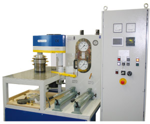
2/2MN Press for use with Piston-Cylinder. Automatic pressure control for upper and lower piston. Manual operation also possible.
Standard design:
We can also offer you the appropriate piston-cylinder modules, if desired.
Semiautomatic control
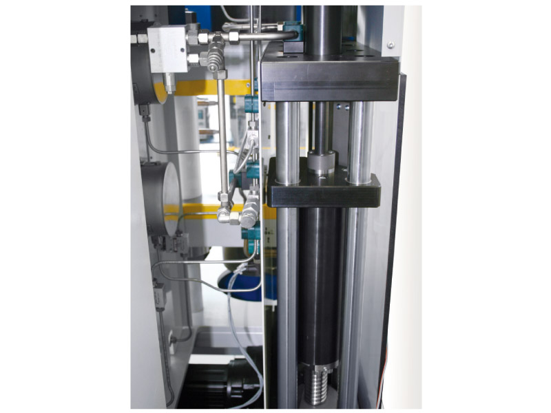
Upper working cylinder:
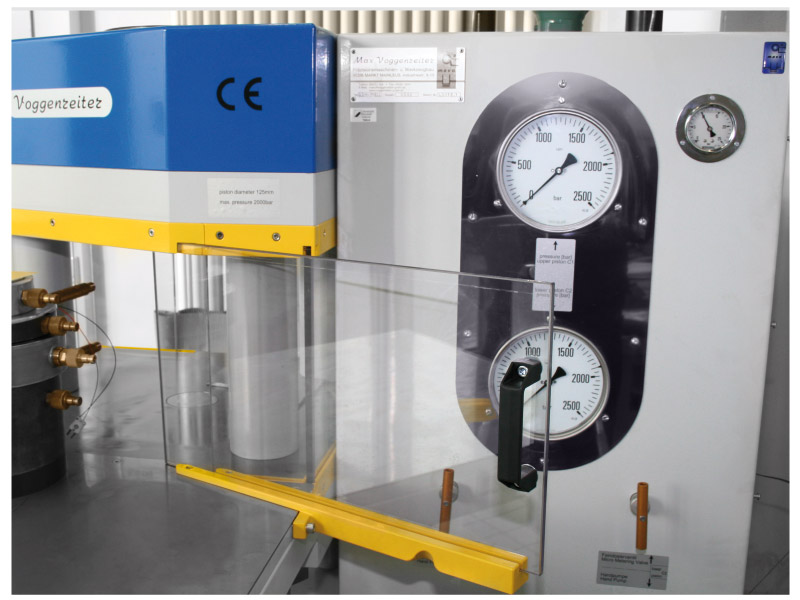
The pressure is not generated by the manual pump but at the touch of a button and with adjustable speed. Thereby the most recent actual pressure value is automatically maintained. When the necessary pressure has been reached, the actual pressure value can be transferred into an automatic program, setting a pressure/time profile with pressure holding time and subsequent automatic pressure relief. Any residual pressure which might still be present after the pressure relief can be carefully released in manual operation. When the initial pressure is at 2,000 bar, the maximum residual pressure is 10%, and full relief is always achieved in the lower pressure range up to approx. 500 bar.
Lower working cylinder:
The pressure is still generated through the manual pump. When the necessary pressure has been reached, the actual pressure value can be transferred into an automatic program where a pressure/time profile with pressure holding time and subsequent automatic pressure relief can be set. In automatic operation, the upper working cylinder can be operated in dependence on the lower working cylinder using a calculation factor. The residual pressure which might still be present after the pressure relief can be carefully released in manual operation. When the initial pressure is at 2,000 bar, the maximum residual pressure is 10% and full relief is always achieved in the lower pressure range up to approx. 500 bar.

Industriestraße 9-10
95336 Mainleus
Telefon +49 (0)92 29 / 306
Fax +49 (0)92 29 / 974163